Chapter 3
From a
syntactical point of view, we can speak of two different
DLIS Logical Record structures for storing information -- namely:
- an Explicitly Formatted Logical Record
- an Indirectly Formatted Logical Record
An EFLR
has a variable-length Logical Record Body (LRB). The format of
the LRB is derived from an analysis of the record itself. An EFLR
is defined in such a general way that it can be used to contain
a wide variety of information related to logging data.
The syntax of an EFLR permits the system or
the application program that is reading DLIS to interpret unambiguously
the information that is contained in the EFLR. The Logical Record
Type in the Logical Record Segment Header permits quick scanning
of Logical Records to locate certain key types of information.
The structures within the EFLR can then be interpreted hierarchically
to get detailed attributes of the information.
Each EFLR
encapsulates a table of information. The rows of the table represent
Objects, and the columns of the table represent
Attributes of the Objects.
At the beginning of the table there is a Template
that defines the columns. The table can be viewed in another way
as a Set of Objects, all of the same Type, defined
by the Template of the Set. Figure 3-1 illustrates a typical EFLR.
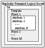
Figure 3-1. Illustration of EFLR Structure
Each EFLR
contains one and only one Set. A Set is interposed between the
EFLR and the Objects in the Set to provide a structure that can
be named, that represents a specific collection of Objects of a
given subtype of the EFLR's Type, and that can be accessed with
the same syntactical machinery that is used to access Objects.
Although an EFLR may contain only one Set, that Set may be one
of several different types implied by the Logical Record Type of
the EFLR.
Formally, a Set consists of one or more Objects
of the same type, preceded by a Template. Each Object has one
or more Attributes. Sets, Objects and Attributes have certain
Characteristics which serve to distinguish one from another.
Templates do not have intrinsic Characteristics. Rather, Templates
are used to specify the presence, order, and default Characteristics
of the Attributes of the Objects in the Set. This permits the
number of explicitly present Characteristics of Attributes in the
Object rows to be reduced -- to zero in some cases.
The basic
syntactic unit of an EFLR is the Component. Components
are used for structural purposes and to carry information describing
the entities, i.e., Set, Objects, and Attributes, that make up
an EFLR.
The following notational conventions are used
in describing Components:
- 1. The notation n‘a..x denotes a value represented
in IDENT or ASCII form (see Appendix B) and consisting of the n
characters a..x preceded by the length n. Examples are
5‘Hello
6‘Origin
24‘This is a string of text
- 2. The notation k&j&n‘a..x denotes
a value represented in OBNAME form (see Appendix B) and consisting
of the Origin reference k followed by a Copy Number j followed
by an Identifier. Examples are
1&0&5‘Depth
(Origin = 1, Copy Number = 0, Object Identifier = Depth)
0&1&8‘Porosity
(Origin = 0, Copy Number = 1, Object Identifier = Porosity)
- 3. The word "null" denotes a value
comprising all bits zero in the minimum number of bytes permitted
by a given Representation Code. Since the equivalent of a null
value depends on its Representation Code, the word "null"
is used when a Representation Code is not explicitly stated.
- 4. The notation 0‘ denotes the null ASCII
or IDENT value, i.e., a zero-length string represented as a single
byte containing the value zero.
- 5. When a bit is specified to be "reserved",
then it must be recorded as a zero bit (not set).
The first
byte of every Component is its Descriptor. A Descriptor
has two parts:
- The Component Role. The Role indicates
what type of entity is described by the Component.
-
The Component Role is defined in Figure 3-2.
The symbolic names in the Role column of Figure 3-2 are used
in illustrations later in this specification.
- The Component Format as defined
in Figures 3-3, 3-4, and 3-5.
-
The Format indicates which Characteristics
of the entity represented by the Component are explicitly present
in the remainder of the Component and the order in which they appear.
Any Characteristic that is not explicitly present assumes a default
value. A Characteristic is explicitly present in a Component if,
and only if, the corresponding bit is set in the Component Format
field. Characteristics appear in a Component in the same order
in which they are defined in the Component Format field. That
is, if bit 4 defines Characteristic A and bit 5 defines Characteristic
-
The Component Format is defined for Set,
Redundant Set, and Replacement Set Components in Figure 3-3, for
Object Components in Figure 3-4, and for Attribute and Invariant
Attribute Components in Figure 3-5. The Absent Attribute has no
Characteristics. Its Component Format field has all bits clear
(not set).
-
The symbolic names in the Symbol column
of the figures are used in illustrations later in this specification.
Except for the Value Characteristic (Figure 3-5), all Characteristics
have fixed Representation Codes. That is, when a given Characteristic
is present in a Component, it is always represented in the same
way. These representations are specified in the figures. Characteristics
may have global default values, also specified in the figures.
The global default value is always assumed when no explicit or
local default value (see §3.2.2.2) is provided.
It is possible for a Component to consist entirely
of its Descriptor, in which case all Characteristics assume default
values.
| Bits 1-3
| Role
| Type of Component
| 000
| ABSATR
| Absent Attribute
|
| 001
| ATTRIB
| Attribute
|
| 010
| INVATR
| Invariant Attribute
|
| 011
| OBJECT
| Object
|
| 100
| reserved
| -
|
| 101
| RDSET
| Redundant Set
|
| 110
| RSET
| Replacement Set
|
| 111
| SET
| Set
Figure 3-2. Definition of Component Role
| |

Figure 3-3. Definition of Characteristics and Component Format
for Set, Redundant Set, and Replacement Set Components
Comments:
- 1.
The Type Characteristic is a dictionary-controlled
name that identifies the type of Objects contained in the Set (see
Chapter 7). A Set's Type Characteristic is used to categorize
the set of Attributes that apply to the Objects in the Set. A
Set’s Type Characteristic must be non-null and must always be explicitly
present in the Set Component. There is no global default.
All Sets have the same structure, and Sets
do not have "types" that distinguish one from another
in that sense. Nevertheless, the phrase "Set Type" is
used in this specification. It is a brief way to say "Set
of Objects of Type ...". The phrase "Object Type"
is also used in this specification. Objects do have types which
distinguish one structure from another (i.e., available list of
Attributes). The Type of an Object is specified by the
Type Characteristic of the Set to which the Object belongs.
- 2.
The Name Characteristic is a user-supplied
name that identifies the Set. The phrases "Set Name"
and "Set Name Characteristic" are used interchangeably.

Figure 3-4.
Definition of Characteristics and Component Format for Object Components
Comments:
- 1.
The Name Characteristic identifies
the Object. For certain Object Types, the Identifier Subfield
of this name is dictionary-controlled. For other Object Types
it is arbitrary. The phrases "Object Name" and "Object
Name Characteristic" are used interchangeably.
This Characteristic must always be present
and must contain a non-null Identifier, so there is no global default
value. That is, every Object has a non-null Name.

Figure 3-5.
Definition of Characteristics and Component Format for Attribute
and Invariant Attribute Components
Comments:
- 1.
The Label Characteristic is a dictionary-controlled
name that identifies the Attribute. The phrases "Attribute
Label", "Attribute Name", and "Attribute Label
Characteristic" are used interchangeably for both Attribute
Components and Invariant Attribute Components.
- 2.
The Count, Representation Code,
Units,; and Value Characteristics are closely related.
A Value consists of zero or more ordered Elements. Each
Element has the same Representation Code, specified by the value
of the Representation Code Characteristic, and the same physical
units of measurement, specified by the Units Characteristic. The
number of Elements that make up the Value is specified by the Count
Characteristic.
The Count Characteristic may be zero. In
this case, the Value Characteristic is undefined, i.e., it is an
Absent Value.
Note that although the Representation Code
Characteristic is always represented in a Component as a USHORT
(one-byte unsigned integer), the global default value for this
Characteristic is the numeric code denoted by the symbol IDENT
(see Appendix B).
The phrases "Attribute Count"
and "Attribute Count Characteristic" are used
interchangeably, as are "Attribute Value" and
"Attribute Value Characteristic",
as are "Attribute Representation Code" and "Attribute
Representation Code Characteristic", as are "Attribute
Units" and "Attribute Units Characteristic".
This paragraph
defines the usage of Components. Illustrations of how Components
can be combined to form a Set are provided in later sections.
A Set Component defines the beginning
of a Set and must be the first Component in the EFLR. The Set
Component contains the Set Type, which is not optional and must
not be null, and the Set Name, which is optional.
A Set consists of one or more Objects, preceded
by a Template. The Objects in a Set share a common set of Attributes.
The order and default Characteristics for these Attributes are
defined in the Template. The Template immediately follows the
Set Component and is terminated by an Object Component. A Template
consists of a collection of Attribute Components and/or Invariant
Attribute Components, mixed in any fashion. These Components define
the structure of the Objects in the Set.
An Object Component defines the beginning
of a new Object. The Object Component contains the Object Name,
which is mandatory. Following the Object Component are a sequence
of Attribute Components and possibly some Absent Attribute Components.
An Object's Attribute Components are terminated by the end of
the Logical Record or by the occurrence of another Object Component.
All Components in the Template must have distinct,
non-null Labels. Attribute Components in the Template specify
local default Characteristics for all Objects in the Set.
Characteristics
not present in Template Attribute Components assume the global
default values defined in Figure 3-5. Invariant Attribute Components,
which may only appear in the Template, represent Invariant
Attributes, i.e., Attributes that are invariant in all
Characteristics for all Objects in the Set.
Therefore, Attribute Components corresponding
to these Invariant Attributes need not and must not appear after
Object Components.
All Attributes in the same "column"
of a Set must have the same Attribute Label, namely, the one specified
in the Template Attribute Component. Therefore, Attribute Components
that follow Object Components must not have Attribute Labels.
The remaining Characteristics may be freely specified by an Object's
Attribute Components. Any Characteristic not present assumes the
local default value as specified in the corresponding Attribute
Component in the Template.
Missing Attribute Components imply that local
defaults should be used for the Characteristics of the corresponding
Attribute. Since Attribute order is important within a Set, only
trailing Attribute Components can be omitted.
An Attribute is considered to be Absent
for an Object when its Attribute Component is replaced by an Absent
Attribute Component. An Absent Attribute is one for
which no information is provided, not even default meaning.
A Redundant Set is an identical copy of some
Set written previously in the same Logical File, including the
Set Name and Type. If a Redundant Set is has a null Name, then
the Set of which it is a copy must be the only Set in the same
Logical File of the same Type, excluding other Redundant Sets,
preceding the given Redundant Set.
A Replacement Set has the same Type and (non-null)
Name, the same Template, and the same Objects (none added, none
deleted) in the same order as a Set written previously in the same
Logical File. However, the Attributes of the Replacement Set reflect
all updates that may have been applied since the original Set was
written. A Replacement Set can be written anywhere in a Logical
File following the original Set that it replaces. There may be
any number of Replacement Sets for a given original Set.
Two views
are used to illustrate EFLRs: symbolic and syntactic. In a symbolic
illustration, the EFLR is represented by a Logical Record Segment
Header symbol followed by a stream of Component symbols followed
by a Logical Record Segment Trailer symbol. The symbols used in
these illustrations are defined in Figure 3-6.
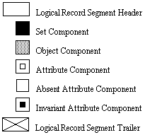
Figure 3-6. Symbolic Representation of Components
A syntactic
illustration shows Component details,
including explicit Characteristics
and their values. The Component Descriptor is represented in the
form R:F, where R is the Role, defined in Figure
3-2, and F is the concatenation of those symbols, defined
in Figures 3-3 through 3-5, specifying which Format bits are set.
Figure 3-7 illustrates an EFLR,
segmented into three Logical Record Segments.
The segmentation is purely arbitrary and is done this way for
illustrative purposes. Although the illustration shows segmentation
on Component and Object boundaries, for example, this is not a
requirement. Logical Record Segmentation may occur at any byte.
The Order in which the Components are illustrated is from left
to right, then top to bottom.
There are seven Attributes specified in the
Template. One of these is an Invariant Attribute, so the column
underneath it is left blank to indicate that no corresponding Attribute
Components appear following the Object Components. The row for
Object 3 contains an Absent Attribute Component, which means that
the third Object has only six Attributes. For the second Object,
on the other hand, the last three Attribute Components have been
left out. This Object still has seven Attributes, but the last
three are identical to the defaults defined in the Template.
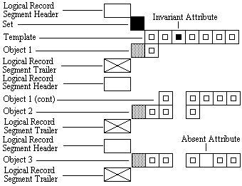
Figure 3-7. Symbolic Illustration of an EFLR
Figure 3-8 is a syntactic illustration of an EFLR. It illustrates a
Set that spans three Logical Record Segments. This is a Set of
Channel Objects (see Chapter 5). Detailed explanation of the entries
in the figure is given in the comments that follow. To make the
comments less awkward and more illustrative, some allusions are
made to the semantic meanings of the Attributes shown in the example
and of other entities. These comments are not intended to define
any semantic meaning, since that is done in later chapters.
Also note that Attributes in the illustration
appear in a different order from that used in Chapter 5 to define
Channel Objects and not all Attributes are used. This emphasizes
the fact that the order in which Attributes appear in the Template
is arbitrary.
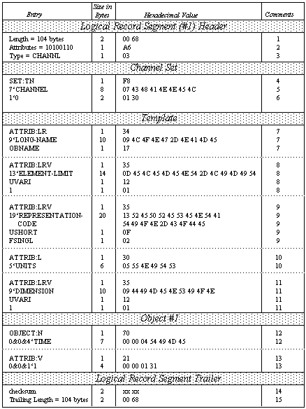
Figure 3-8. Syntactic Illustration of an EFLR
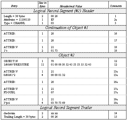
Figure 3-8 (cont). Syntactic Illustration of an EFLR
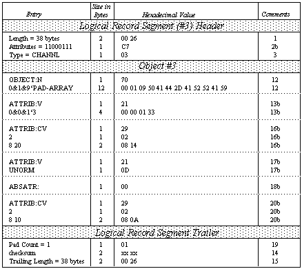
Figure 3-8 (cont). Syntactic Illustration of an EFLR
Comments:
- 1. Each EFLR begins with a length, which
includes the LRSH, the LRB, and the LRST.
- 2. The Logical Record Segment Attribute bits
for Segment #1 indicate an EFLR structure (bit 1), no predecessor
segment (bit 2), a successor segment (bit 3), no encryption (bit
4), no Encryption Packet (bit 5), a checksum (bit 6), a Trailing
Length (bit 7), and no Padding (bit 8).
- 2a. The Logical Record Segment Attribute
bits for Segment #2 indicate an EFLR structure (bit 1), a predecessor
segment (bit 2), a successor segment (bit 3), no encryption (bit
4), no Encryption Packet (bit 5), a checksum (bit 6), a Trailing
Length (bit 7), and no Padding (bit 8).
- 2b. The Logical Record Segment Attribute
bits for Segment #3 indicate an EFLR structure (bit 1), a predecessor
segment (bit 2), no successor segment (bit 3), no encryption (bit
4), no Encryption Packet (bit 5), a checksum (bit 6), a Trailing
Length (bit 7), and Padding (bit 8).
- 3. All Segments specify the same Logical
Record Type, denoted by the term CHANNL. The numeric value (03)
is obtained from Appendix A
- 4. The Set Component indicates presence of
a Type and a Name.
- 5. The Object Type is CHANNEL (see Chapter
5).
- 6. The Set Name is "0".
- 7. Template Component #1 specifies the Attribute
labelled Long-Name and its local default Representation Code =
OBNAME. The remaining defaults (Count = 1, Units = 0‘, and Value
= null) are taken from the global defaults specified in Figure
3-5.
- 8. Template Component #2 specifies the Attribute
labelled Element-Limit, its local default Representation Code =
UVARI, and its local default Value = 1. The global default Count
= 1 is assumed. Thus, the local defaults indicate a scalar sample.
- 9. Template Component #3 specifies the Attribute
labelled Representation-Code and its local default Representation
Code = USHORT and Value = FSINGL. Note that the Value of this
Attribute is a Representation Code, which semantically is applied
to some other entity, in this case to the sample elements of some
Channel.
- 10. Template Component #4 specifies the Attribute
labelled Units. It does not explicitly specify any other Characteristics,
so global defaults apply.
- 11. Template Component #5 specifies the Attribute
labelled Dimension and its local default Representation Code =
UVARI and Value = 1. The global default Count = 1 is assumed.
- 12. The Object Component for Object #1 precedes
its own Attribute Components and terminates the Template. The
Object Component for Object #2 precedes its own Attribute Components
and terminates the Attribute Components of Object #1. The Object
Component for Object #3 precedes its own Attribute Components and
terminates the Attribute Components for Object #2.
These Objects are named, respectively, "Time"
(with Origin 0, Copy Number 0), "Pressure" (with Origin
1, Copy Number 0), and "Pad-Array" (with Origin 0, Copy
Number 1).
- 13. The Long-Name Attribute for Object #1
references the Object named "1" from Origin 0 with Copy
Number 0. The Type of the referenced Object (namely, Long-Name)
is specified by definition for this Attribute.
- 13a. The Long-Name Attribute for Object #2
references the Object named "2" from Origin 0 with Copy
Number 0.
- 13b. The Long-Name Attribute for Object #3
references the Object named "3" from Origin 0 with Copy
Number 0.
- 14. Each Logical Record Segment Trailer contains
a two-byte checksum.
- 15. Each Logical Record Segment Trailer contains
a Trailing Length, which has a value equal to the Logical Record
Segment Length in the LRSH.
- 16. The Element-Limit Attribute for Object
#1 assumes all the local default Characteristics.
- 16a. The Element-Limit Attribute for Object
#2 assumes all the local default Characteristics.
- 16b. The Element-Limit Attribute for Object
#3 has Count = 2 and Value = {8 20}. This indicates that the corresponding
sample value may be 1 or 2-dimensional, may have up to 8 array
elements along the first dimension and up to 20 array elements
along the second dimension.
- 17. The Representation-Code Attribute for
Object #1 assumes all the local default Characteristics.
- 17a. The Representation-Code Attribute for
Object #2 has the Value FDOUBL.
- 17b. The Representation-Code Attribute for
Object #3 has the Value UNORM.
- 18. The Units Attribute for Object #1 has
the Value s (second).
- 18a. The Units Attribute for Object #2 has
the Value psi (pound per square inch).
- 18b. The Absent Attribute Component for Object
#3 indicates that no Units Attribute is specified for this Object.
- 19. Padding is required in the third Logical
Record Segment to make its length come out even. In this case,
only one Padding Byte, the Pad Count, is required.
- 20. There is no Attribute Component for Object
#1 for the Dimension Attribute. Therefore the Dimension Attribute
assumes all the local default Characteristics.
- 20a. There is no Attribute Component for
Object #2 for the Dimension Attribute. Therefore the Dimension
Attribute assumes all the local default Characteristics.
- 20b. The Dimension Attribute for Object #3
has Count = 2 and Value = {8 10}, i.e., a two-Element Value. The
first Element is the integer 8 and the second Element is the integer
10. Semantically (as is specified in Chapter 5), this indicates
that the samples of Channel Pad-Array (Copy 1) are 2-dimensional
arrays with 8 elements in the first dimension and 10 in the second
for a total of 80 elements.
The format
of the Logical Record Body of an Indirectly Formatted Logical Record
cannot be interpreted from an analysis of the record itself. Instead,
it is defined by the contents of associated EFLRs.
Typically, a stream of data is encapsulated
in a sequence of IFLRs. There can be several multiplexed sequences
of IFLRs in a single Logical File. A referencing mechanism is
used to sort them out. This characteristic is particularly useful
for recording log data, which is acquired as a sequence of identically-formatted
packets, the number of which is unknown by the system when acquisition
begins.
Figure
3-9 defines the structure of the Logical Record Body of an Indirectly
Formatted Logical Record.

Figure 3-9. Structure of an Indirectly Formatted Logical Record
Comments:
- 1. The Data Descriptor Reference is
the Name of an Object in an EFLR. The Logical Record Type in the
Logical Record Segment Header must determine uniquely the Type
of the Object that is referenced.
The referenced Object and all other Objects
that are used to define the format of the Indirectly Formatted
Data must be in the same Logical File as this IFLR and must
precede this IFLR.
- 2. The Indirectly Formatted Data is
a set of 8-bit bytes, extending to the end of the Logical Record
Body. This set contains the data. The specific format of this
data is defined by the Object named in the Data Descriptor Reference
and by any other Objects that are associated with that Object.


